by M. Higgins and C. Swift * (10/14)
Revised by Kurt Jones**
Quick Facts….
- Prepare your sprinkler system for winter by expelling all the water from the irrigation system and equipment.
- Do not trust manual or automatic drain valves. The system should be blown out with pressurized air.
- To determine the best sized compressor for your system, know the gallons per minute (GPM) that flow through each zone.
- If your irrigation system is attached to domestic water, it is required to have a backflow prevention device.
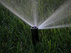
The concept of preparing your sprinkler system for winter must be done correctly to assure there are no costly repairs and replacements to make in the spring at system start-up. The process consists of expelling all the water from the irrigation system and equipment. This is necessary because water freezing in the irrigation system will break pipes, fittings, valves, sprinklers, pumps, and other system components.
Most substances contract as they get cold; however, when water cools, it contracts only until it reaches a temperature of 39 degrees Fahrenheit. Upon further cooling to 32 degrees Fahrenheit, water expands as it turns to ice. Water expands and increases in volume by one-eleventh, so 11 cubic feet of water will form approximately 12 cubic feet of ice. This expansion force is sufficient to cause pipes and fittings to burst valves to crack, and sprinkler and pump cases to split open.
Draining the System
Draining the system may be accomplished by the use of either manual or automatic drain valves which rely on gravity to purge water from the system. These valves rely on a properly-installed system laid to grade with no humps in the pipe to trap water in low areas. This method is not recommended since sub-surface pipes have a tendency to shift with time and there is no way to visually inspect lines once draining is complete. The only positive way to be sure enough water has been expelled from the system is by using compressed air to “blow” the water out.
Systems with electric valves must be blown out with pressurized air. There is no other way to drain the water off the top of the diaphragm of the valve.
Air volume is as critical as air pressure. If an insufficient volume of air is used, after forcing some water out, the air will ride over the top of the water. This will result in the remaining water draining into low spots and subjecting the system to freeze damage. Ideal pressures are in the range of 40 to 80 pounds per square inch (psi) for the air compressor with 80 psi being the maximum for rigid PVC pipe and 50 psi for polyethylene pipe (flexible black pipe). Set the pressure regulator on the air compressor accordingly. If the pressure is in excess of what the nozzles are rated, the excessive pressure will blow the sprinkler nozzles off and could cause other damage. The rating of the nozzles is available at the manufacturer’s home web page.
Rule of thumb: If the sprinkler heads stay up after the water is blown out and compressed air continues to flow through the system, you are using the right size compressor.
The idea is to “blow” your system out using only the volume of air necessary. If you normally run one zone at a time when irrigating, the system should blow out the same way. If you try to do more, the excess velocity of flow and added friction will heat up the pipe and fittings to a point where they could possibly melt. If the pipe and fittings do not burst during this operation, they could be damaged and reduce their life.

Figure 1: Stop and Waste |
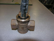
Figure 2: Stop and Waste with a key |
To figure out the best sized compressor for the system you need to know the gallons per minute (GPM) that flow through each zone in the system. When the system was designed it should have had a GPM rating for each zone marked on the irrigation plan. If this information is not available, a quick estimate of GPM per zone can be made by adding up the GPM rating for each sprinkler head nozzle on the zone. GPM data is available on the manufacturer’s web site.
Divide GPM by 7.5 to determine the cubic feet per minute (CFM) needed. This is the ideal sized compressor to “blow out” your system.
GPM divided by 7.5 gallons = CFM needed
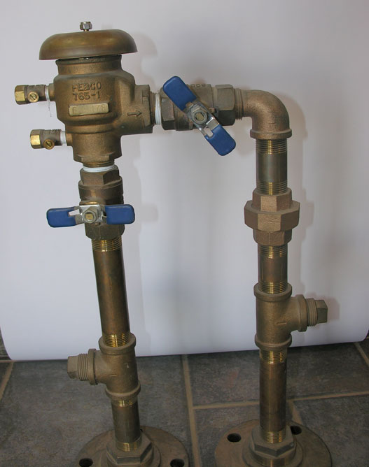
Figure 3a: Left Photo: Pressure vacuum backflow device (PVB) |
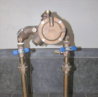
Figure 3b:Right Photo – Reduced Pressure back flow device (RP). Blue handles designate isolation ball valves. Note blowout fittings (tees with threaded plugs) on either side of the device. |
For example, if the system is designed for 30 psi and 20 gallons per minute per zone, divide 20 by 7.5. The answer is 2.66 cubic feet per minute. A compressor capable of providing 2.66 cfm (cubic feet per minute) at 30 psi (pounds per square inch) will be required. Under-sized compressors will take a lot longer and work harder to deliver the required volume and pressure to purge your system. Larger compressors stand the risk of pressurizing too quickly and causing damage to the system, though an air pressure regulator on the outlet of the compressor can overcome this problem.
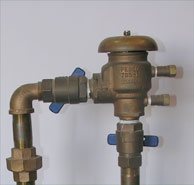
Figure 4: Both ball valves and test cocks should be exercised back and forth several times. |
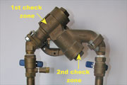
Figure 5: Open test cocks (1st check zone) and remove the check cap (2nd check zone. |
Turning off the Water Supply
Start by turning off the water supply to your system. A stop and waste valve or drain of some type should have been installed between the water supply and the backflow device. Turn this off. This may be located in a basement, crawlspace, or valve box underground. In many cases, a stop and waste valve will be installed below ground. The stop and waste may be 5 feet down, so a long key may be necessary. Do not force this valve while opening or closing it.
Drain the Pump
If the system has a pump, it should be drained, removed from the system and stored inside. If this is not possible, drain the pump and wrap it to insulate it from the weather.
Winterizing the Backflow Device
If your irrigation system is attached to domestic water, it is required to have a backflow prevention device.
Atmospheric Vacuum Breaker (AVB) devices are installed downstream of each valve and are winterized with compressed air when the zone is blown out. AVBs may not be legal in your area. Check with your water district, planning/building department, or county health department.
Pressure Vacuum Breaker (PVB) or Reduced Pressure (RP) backflow prevention devices must never be blown out with compressed air. The rubber seals inside can easily melt from the heat of the air.
Draining a PVB
- A properly designed and installed PVB should drain easily if both the riser before and after the backflow preventer are empty of water. After the system is blown out, both ball valves and test cocks (these protrude from the side) should be exercised back and forth several times. Leave these in a half-open position for the winter. Ball valves that are either fully closed or fully open tend to trap water, expand and cause damage. In the spring, close the test cocks and ball valves before pressurizing the system. Once the water supply to the PVB is turned on, open the ball valves slowly to pressurize the rest of the irrigation system. Opening the ball valves slowly will prevent damage to the system that can be caused by water hammer.
Draining an RP Device
The internal passages of the Reduced Pressure device must be drained of all water. There are two check valves in an RP that need to be drained separately. This is accomplished as follows:
- Slowly close the main shutoff valve upstream of the device.
- Drain the system of all water upstream of the device. This will require opening the stop and waste or other drain.
- For the first check zone (closest to the water supply), open test cocks #2 and #3. This will drain all the water between the first and second check valves.
- For the second check zone (downstream) remove the check cap, spring and disk holder. (see photo above) All water downstream of the second check will drain through the body. Replace disk, spring and check cap.
- If the device is equipped with optional drain plugs, remove the plugs and test cocks #2 and #3.
- Leave the isolation ball valves approximately 45 degrees while draining the assembly. Leave the ball valves in this position for the winter.
- The ball valves should be fully closed when the system is pressurized in the spring. Always open and close the ball valves slowly to prevent damage to the system caused by water hammer.
Winterizing the Rest of the Irrigation System
To blow out the irrigation system, connect the compressor to the downstream blowout fitting. Ensure the isolation ball cock on the downstream side of the backflow device is closed. Remember to turn it back to the half-open, half-closed position after blowing out the irrigation system. Start one or more of the zones/stations at the irrigation controller, turn on the compressor to the proper pressure and blow out the system.
If the backflow device does not have a blowout fitting on the downstream side, one will need to be added before the irrigation system can be blown out.
Other Tips
- Each zone/station should be blown out twice to make sure all the water is purged from the system. It is better to use two short cycles per station/zone than to have one long cycle.
- Once a zone is “blown out”, avoid blowing that zone out again. Compressed air moving through dry pipes causes friction and heat which could cause damage.
- After purging the system of all water, leave all the valves on your backflow preventer half open. This will help keep the backflow preventer from freezing and splitting during the winter. If the PVB test cocks are left open, be sure to close them before turning the system on in the spring.
- Connecting the compressor’s air line to a metal fitting instead of PVC will help dissipate some of the heat during the blowout process.
- The irrigation controller should remain powered during the winter. Do not unplug the controller. Heat from the transformer can help reduce moisture and protect components in the controller from corrosion. The controller should be programmed to run through a minimum cycle once a week to help keep solenoid plungers from sticking.
- Blowing out sprinkler systems can occasionally upset pets due to “whistling.” Care should be taken to protect pets from running off during winterization.
Final Thought and Warning
It is important to remember it is much less costly and much less labor intensive to properly and efficiently prepare the system in the fall than to repair damaged fittings, piping, valves, sprinklers and other components in the spring.
CAUTION! WEAR PROPER EYE PROTECTION!
*M. Higgins, Grand Junction Pipe and Supply, Grand Junction, CO.; C.E. Swift, former Colorado State University Extension, horticulture agent **Kurt Jones, Colorado State University Extension, agent, natural resources and agriculture, Chaffee County. 4/03. Revised 10/14.
Go to top of this page.